
Slack loop formation disrupts tight, uniform winding on spools. Cable develops visible sags between payoff and take-up points. These sags grow into loose loops during high-speed runs. Final coils exhibit irregular layers, crossovers, and soft spots. Storage stability suffers. Transport risks increase. Rejection rates reach 20-30% in severe cases.
Exact Mechanics of Slack Loop Development
Tension drops below critical threshold trigger instantaneous slack. Cable forms catenary curves under self-weight. Curve depth increases with span length and material mass per meter. Loop amplitude escalates when payoff speed momentarily exceeds take-up speed by even 1-3%. Dynamic imbalance accumulates. Pendulum-like oscillations emerge at natural frequencies matching machine cycle times. Resonance amplifies sags until loops contact frames or guides.
In-Depth Tension-Related Causes
Sensor drift causes gradual tension decay. Load cells lose 4-7% accuracy after 4000-6000 hours without recalibration. Dancer arms develop play in pivots. Friction coefficients rise from dust accumulation. Tension setpoint deviates during speed ramps. Acceleration phases show 10-15% undershoot in open-loop systems. PID controllers without feedforward tuning overshoot or hunt around target values.
Excessive tension stretches conductors beyond elastic limits. Copper wires yield at 12-18% elongation. Permanent deformation creates memory effects. Subsequent winding produces uneven layers prone to slack pockets.
Insufficient tension allows material to droop freely. Loops form when hanging length exceeds 1.5-2 meters without support. Thin gauges below 2 mm² sag noticeably at tensions under 5% of breaking strength.
Speed Synchronization Failures in Detail
Line components operate at mismatched velocities under varying loads. Uncoiler drum slows 3-6% due to inertia when spool diameter decreases. Coiler maintains constant linear speed. Excess cable feeds into free-hanging section. Buffer zones overflow. Intended control loops saturate. Material piles up in uncontrolled sags.
Traverse mechanisms lag during direction reversals. Traverse speed mismatches winding speed by fractions of a percent. Overlaps or gaps appear. Localized tension drops create slack at reversal points.
Variable frequency drives without torque compensation struggle with changing spool inertia. Speed regulation error grows as coil builds. Fluctuations reach ±5% in poorly tuned systems.
Component Wear and Geometric Effects
Guide rollers develop elliptical cross-sections after prolonged use. Groove depth exceeds 0.5 mm. Cable experiences lateral slip. Path length varies cyclically. Tension oscillates with each rotation. Slack forms in low-tension quadrants.
Misalignment by 0.5-1.5 degrees introduces asymmetric drag. Cable pulls to one side. Inner layers compress while outer layers slacken. Cross-winding defects compound loop formation.
Spool flanges warp under thermal cycling or mechanical stress. Winding diameter varies across width. Tension gradients develop. Loops concentrate at flange edges.
Material-Specific Behaviors
Aluminum conductors show lower yield strength than copper. Slack forms at lower tensions. Recovery from stretch remains incomplete. Viscoelastic jackets on PVC or XLPE cables exhibit creep under sustained low tension. Sags persist after tension restores.
Multi-strand cables twist internally when tension fluctuates. Individual wires migrate. Bundle diameter changes dynamically. Effective bending stiffness drops. Loops form more readily in flexible constructions.
High-temperature runs above 30°C reduce material modulus. Sag depth increases proportionally. Thermal expansion adds 0.1-0.3% length variation. Loops grow without adjustment.

Comprehensive Diagnostic Protocols
Install high-frequency tension loggers sampling at 200-500 Hz. Capture transients during speed changes. Identify drop magnitude and duration. Correlate events with loop visuals from synchronized cameras.
Use 1000 fps video recording. Analyze frame-by-frame sag initiation. Calculate catenary parameters using cable linear density and span. Compare against Euler buckling criteria for hanging sections.
Perform profilometry on guides every 1000 hours. Map groove wear patterns. Quantify radius changes and edge buildup. Laser-align rollers to 0.05 mm precision under operational load.
Run material hysteresis tests on laboratory winders. Apply tension cycles from 2% to 15% of yield. Measure residual elongation. Flag batches with high creep for adjusted parameters.
Vibration spectrum analysis detects resonance peaks. Accelerometers on frames reveal frequencies matching loop pendulum periods. Damping modifications target specific modes.
Precision Correction Techniques
Deploy closed-loop servo tensioners with load cell feedback. Tune PID gains for <±2% deviation across 5-200 m/min range. Add velocity feedforward to anticipate speed changes. Implement gain scheduling based on spool diameter.
Synchronize drives via electronic line shafting. Master coiler sets reference. Slaves follow with ratio compensation for stretch and diameter. Torque mode on payoff absorbs inertia variations.
Upgrade guides to precision-ground ceramic composites. Maintain groove clearance at 12-18% of cable diameter. Minimize friction to <0.05 coefficient.
Integrate active loop sensors. Laser or ultrasonic transducers measure sag height continuously. Output modulates payoff speed. Maintain loop depth at 1.1-1.6 times minimum bend radius. Prevent overflow.
Add low-inertia dancer systems with magnetic particle brakes. Dampen oscillations via velocity feedback. Reduce natural frequency below operating range.
Fine-tune traverse and winding ratios. Achieve lay factor of 0.85-0.93 for optimal fill without pressure buildup. Alternate traverse patterns for multi-layer stability.
Sustained Prevention Framework
Establish condition-based maintenance. Trend sensor drift monthly. Replace at 5% accuracy loss. Realign quarterly with thermal compensation.
Stabilize ambient conditions. Target 22±2°C and 50±5% RH. Install localized cooling for tension zones.
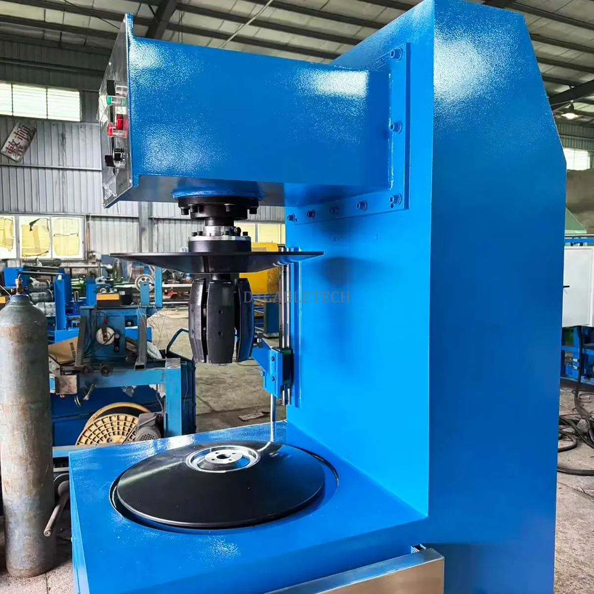
Select coilers with native anti-slack architecture. Dosing Cabletech systems feature dual-zone tension regulation, predictive synchronization, and adaptive loop control. Deployments show 45-60% reduction in slack defects.
Enforce structured operator protocols. Mandate daily tension profiling. Require certification in diagnostic interpretation.
Dosing Cabletech engineers advanced coiling solutions for demanding wire and cable applications. Explore detailed specifications dxcabletech. Secure consistent, high-quality coils through integrated precision and rigorous control. Contact for site-specific assessments and upgrades.
Explore the complete cable manufacturing system:
→ Cable Manufacturing Process & Equipment Guide